Learning to Love Electrical Schematics
I’ve never liked electrical schematics. And, for much of my time working as a technician, I refused to use them.
Who needs an electrical schematic anyway, right? Checking for voltage at the wall and components is easy. Checking amp draw with a current clamp is simple and so is disconnecting components and checking for continuity and resistance.
I was wrong. And I wasted so much time unnecessarily disconnecting components and scratching my head at voltage readings that didn’t make sense, not realizing that an electrical schematic had the answers.
Yes, electrical schematics look imposing. Yes, they take time and effort to decode. But troubleshooting often involves finding what is broken by determining what isn’t broken, and few tools provide more information about the proper function of electrical circuits than an electrical schematic.
Navigating the maze
Much of my resistance to using electrical schematics was because I found them difficult to read. At first glance, they look like mazes. I hadn’t yet learned the trick of starting with a printed paper copy and tracing electrical paths with a pen or stylus.
Tracing the paths helps narrow your focus to the portion of the maze that’s relevant to the problem you’re troubleshooting and helps keep you from getting lost or distracted in the process. How do you find the relevant portion of the electrical schematic? One way is to locate a key component in the circuit, like a heating element, autofill solenoid valve, or brew valve. Standard symbols are used to represent different components, and most diagrams also include a key which identifies them by number or letter. With that information, finding the component is a quick game of “Where’s Waldo?” and you can trace the rest of the circuit from there.
Getting wires crossed
Let’s talk about all those lines. Though different manufacturers approach electrical schematics in different ways, there are some common practices. Navigating the electrical schematic maze is easier with them in mind.
Lines represent electrical connections between components. In coffee equipment electrical circuits, this usually means wires, though they may be drawn longer or shorter than the actual wires used so the schematic can be read more easily.
Lines on the schematic often meet or cross each other. If there is a dot where they meet, that represents an electrical connection point called a node. This is like an intersection on a road – a car could turn or go straight. If there is no dot, there is no electrical connection at that crossing point. Think highway overpass: the roads don’t intersect. Designers will sometimes add half-circle “line hops” to make it clearer that one line is jumping over the other.
Troubleshooting using a schematic
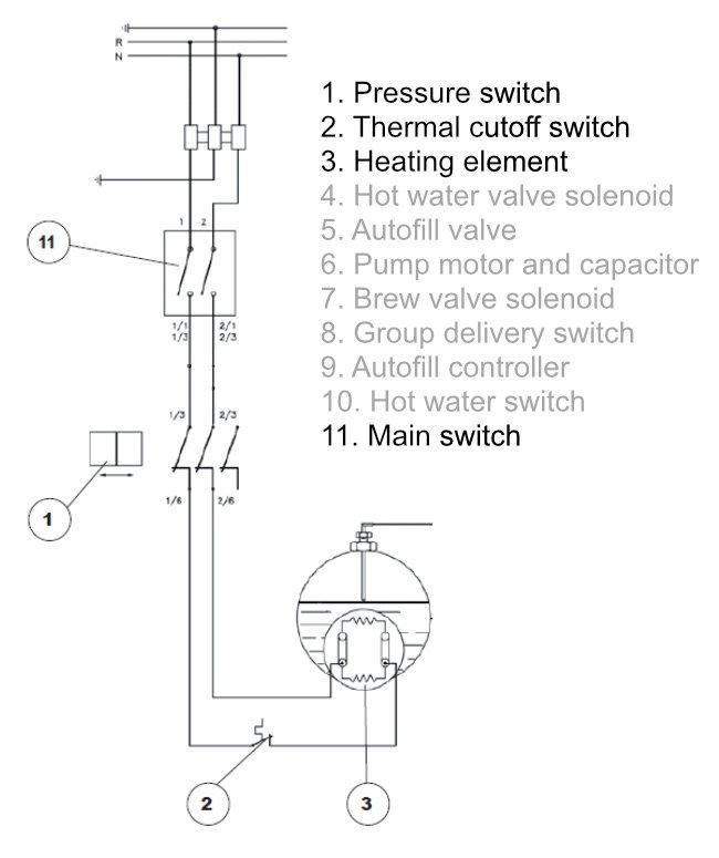
How can an electrical schematic help a technician troubleshoot a malfunctioning circuit? Let’s look at part of the electrical schematic for a Nuova Simonelli Appia II single group semiautomatic (110v).
This electrical schematic shows that current flows from the terminal block through the main switch, the pressure switch, the thermal cutoff switch, the heating element, then back through the pressure switch and main switch to the terminal block. That’s a short list of components which could be responsible if the machine was on but not heating.
The schematic can also show the technician which points should show a difference in electrical potential, aka voltage. All the lines connected at a node are assumed to be perfect conductors and will have the same electrical potential until they hit a component that has resistance, like a heating element or solenoid coil, or open switch. Since the only resistance in this circuit is the heating element, measuring between the two heating element nodes should show supply voltage – 110 volts in this case.
Using that same logic, the technician can also use this schematic to see that there should be no potential difference (0 volts) between any pair of nodes that come before the heating element in the circuit, or any pair that comes after the heating element in the circuit. If any voltage is measured between a set of terminals of a closed pressure switch or thermal cutoff switch, that means there is resistance there – and probably a malfunction. That means we can find malfunctioning components quickly, without disconnecting them.
Experienced technicians already understand simple circuits like this well enough that this electrical schematic may not be helpful. But schematics can be very useful for new techs or when approaching more complex circuits.
Learning to love electrical schematics
Electrical schematics do take some time to read and learn to use properly. However, the information these mazes provide can help the willing technician better understand the function of electrical circuits and make sense of the numbers on their multimeter. While I still don’t love them, they are absolutely a tool I’m happy to use.

